A commercial interior partition is a fire-rated wall assembly only when the entire tested system is built together: the specified gypsum board layers, steel studs, screw schedule, staggered joints, head-of-wall seal, and listed firestops at every opening. Individual materials do not possess fire resistance on their own; a fire-resistance rating is assigned in hours to a complete building element on the basis of a standard fire test or approval system and a certification listing that sets its installation tolerances.
Store buyers comparing fire rated wall panels or searching for class a fire rated wall panels run into trouble when a single board label or a surface flame-spread product listing gets treated like a complete compartment barrier. Materials themselves are not fire-resistance rated, and citing a product with a flame-spread rating is unacceptable where local building and fire codes require a fire-resistance-rated separation or a listed firestop. Locally applicable building and fire codes and the approved project drawings establish the required wall class and hourly duration between a sales floor, stockroom, corridor, or neighboring tenancy.
For facility managers and shop owners working through tenant build-outs across our commercial spaces guides and the storefront operations blog, partition details belong on the drawing set before framing starts. Temporary work-zone barriers, delivery hours, and floor reopening rules during construction live in planning a partial refit while the shop stays open, while washable room surfaces and replacement triggers belong in busy-room finishes for washing, wear, and replacement.
What makes a partition a fire-rated wall assembly under ASTM E119?
Building codes require compartments inside buildings to be separated by fire-rated barriers or partitions rated on their resistance to the passage of heat and smoke. Keeping those interior partitions intact prevents flame spread, keeps egress paths available, and increases safe time in places of refuge. Full-size fire resistance tests are preferred over small-scale material tests because full-scale exposure assesses the whole construction method, including thermal expansion, shrinkage, local damage, and deformation under load.
In the United States, ASTM E119 is the standard fire-test procedure used to evaluate masonry units and composite building assemblies, including loadbearing and non-loadbearing walls and partitions that form permanent integral parts of a finished building. Residential and commercial fire testing uses a building-elements time-temperature curve characterized by standards that include ASTM E119. In real-scale NIST compartment-fire testing of a non-load-bearing steel-stud gypsum wall assembly, temperatures were tracked across three zones: at the exposed face, inside the stud cavity, and at the unexposed face.
Three traditional fire limit states govern barrier performance: heat transmission that causes an unacceptable temperature rise on the unexposed surface (insulation), breach of the barrier from loss of integrity, and loss of load-bearing capacity (stability). Under ASTM E119 as quoted in NIST structural fire-resistance design guidance, the average temperature rise above ambient on the unexposed side of a barrier is limited to 139 °C. Passive-fire-protection reference literature separately describes a typical fire-test objective of keeping the protected side at or below 140 °C for walls, floors, and electrical circuits that require a fire-resistance rating, whereas structural fire protection on a steel beam or column uses a typical test objective of about 538 °C, where steel yield strength drops enough for structural collapse to occur. That 538 °C figure applies to structural steel elements such as beams and columns rather than the unexposed side of a gypsum partition.
| ASTM E119 wall and partition check | What the public scope and significance cover or exclude |
|---|---|
| Fire containment and integrity duration | Evaluates the duration for which covered walls and partitions contain a fire, retain structural integrity, or exhibit both properties during a predetermined controlled furnace exposure. |
| Wall and partition measurements | Provides for measurement of the transmission of heat and measurement of the transmission of hot gases through the wall or partition specimen, plus load-carrying ability for loadbearing elements. |
| Conditional hose stream | Follows the fire exposure, when required, with a specified standard fire hose stream applied in accordance with Practice E2226. |
| Smoke generation and smoke passage | Does not evaluate how much the specimen contributes to fire hazard by generating smoke or toxic gases, and does not measure control or limitation of smoke passage through the specimen. |
| Perimeter floor-wall and wall-wall joints | Does not simulate the fire behavior of joints between building elements, such as floor-wall or wall-wall connections. |
| Electrical outlets and plumbing pipes | Does not evaluate conventional openings such as electrical receptacle outlets or plumbing pipe unless built into the tested construction, pointing instead to Test Method E814 for fire stops. |
Furnace ratings also carry strict operational boundaries. Fire-resistance durations obtained in furnaces do not coincide with actual escape or safety times; they give relative guidance comparing building elements under controlled test conditions because real fires vary with fuel loading, ventilation, compartment size and configuration, and compartment heat sinks. If critical environmental conditions are not satisfied, an assembly may not be eligible for a fire-resistance rating. Under ASTM E119, any change in specimen size, materials, or method of assembly changes the fire-test response and requires evaluation before field use, and an ASTM E119 classification is not a determination that the assembly remains suitable for use after fire exposure.
How do Type X and Type C gypsum layers, studs, and joints work?
Gypsum board consists of a non-combustible core, usually not less than 65 % gypsum, laminated between paper surfaces. Its fire delay comes from calcium sulfate dihydrate in the core, which holds chemically bound water of crystallization equal to about 21% by weight alongside a small amount of free moisture. When fire heats the exposed face, calcination converts the dihydrate into gypsum hemihydrate across temperatures of 80 °C to 150 °C, releasing and evaporating that bound water in an endothermic reaction that absorbs thermal energy and retards heat transfer. While that bound water is being driven out, protected steel studs directly behind the fire-exposed gypsum board remain near the boiling temperature of water, around 100 °C.
At higher temperatures, Type X and Type C boards stay in place longer than regular gypsum board because of reduced shrinkage and a stronger core. Gypsum board shrinks by up to 1.5% by the time it reaches 600 °C, and because screws and framing restrain that movement, tensile stresses build up and crack the board across the field or around the attachment screws. Type X and Type C boards are the fire-resistant gypsum products most widely used in North America, formulated with denser, stronger cores to give building systems greater fire resistance than regular gypsum board of the same thickness:
- Type X gypsum board mixes glass reinforcement fibers into the gypsum core; those fibers reduce the size of cracks that form as water is driven off so the dehydrated panels stay in place longer as a heat and flame shield.
- Type C gypsum panels provide stronger fire resistance than Type X by combining a higher density of glass fibers with vermiculite, a shrinkage-compensating additive that expands at roughly the gypsum calcination temperature so the core stays more dimensionally stable in fire.
Adding drywall layers in documented design or certification listing catalogues increases the fire-resistance rating of a drywall fire-barrier assembly, with encyclopedia upper examples reaching up to four hours for walls and three hours for floor and ceiling assemblies. Even so, layer count, board thickness, steel stud depth, screw length, and joint stagger are locked together inside each tested listing. NIST structural fire-resistance guidance quotes the two ASTM C36-97 reference assemblies used to define Type X gypsum board, and comparing them side by side shows why field crews cannot swap parts between one-hour and two-hour walls:
| Assembly feature | ASTM C36-97 one-hour Type X definition assembly | ASTM C36-97 two-hour Type X definition assembly |
|---|---|---|
| Framing and stud spacing | Non-load-bearing cold-formed galvanized steel studs measuring 92x35x0.5 mm spaced 600 mm on center. | Non-load-bearing cold-formed galvanized steel studs measuring 64x35x0.5 mm spaced 600 mm on center. |
| Gypsum board layers and width | Single layer of 15.9 mm thick gypsum board on each side, using 1200 mm wide sheets. | Two layers of 12.7 mm thick gypsum board on each side, using 1200 mm wide sheets. |
| Base-layer screw schedule | 25 mm long drywall screws spaced 200 mm on center along board edges and ends, and 300 mm on center along intermediate studs. | 25 mm long drywall screws spaced 300 mm on center along board edges, ends, and intermediate studs. |
| Face-layer screw schedule | Single-layer construction on each face (no separate second layer). | 41 mm long drywall screws spaced 300 mm on center along board edges, ends, and intermediate studs. |
| Joint orientation and stagger | All joints oriented parallel to and located over studs, and staggered on opposite sides of the assembly. | Base-layer joints over studs and staggered on opposite sides; face-layer joints over studs, offset 600 mm from base-layer joints, and staggered on opposite sides. |
Those two ASTM C36-97 configurations are standard material-definition assemblies rather than a universal menu for every storefront wall. Notice that the two-hour definition assembly uses a 64x35x0.5 mm stud and two 12.7 mm boards per side rather than simply screwing a second 15.9 mm sheet onto the 92x35x0.5 mm one-hour stud frame. On an actual store project, installers build the exact listed wall assembly named on the approved drawings and certification listing catalogue, matching its tolerances and materials.
Should a rated store wall run to the deck or stop at the ceiling?
Because ASTM E119 does not simulate floor-wall or wall-wall connections, stopping a rated drywall partition at a drop-ceiling grid without checking the wall class can leave an open path for fire and smoke through the plenum above the shop. Compartmentation subdivides a building into enclosed fire compartments separated by rated construction under local building codes to limit the spread of fire, smoke, and combustion gases. Construction references group fire-rated walls into three main classifications with distinct structural and continuity rules:
- Fire walls have a prescribed fire-resistance duration and independent structural stability, allowing an unstable fire-damaged building section to break or fall away without collapsing the wall.
- Fire barriers (typically constructed as drywall or gypsum board partitions on wood or metal studs) are rated wall assemblies that are not structurally self-sufficient, and they run continuously through concealed spaces, such as the space above a suspended ceiling, up to the floor deck or roof deck above.
- Fire partitions are also rated wall assemblies without independent structural stability, and they are not required to extend through concealed spaces if the construction assembly forming the bottom of the concealed space, such as the ceiling, carries a fire-resistance rating at least equal to or greater than the fire partition.
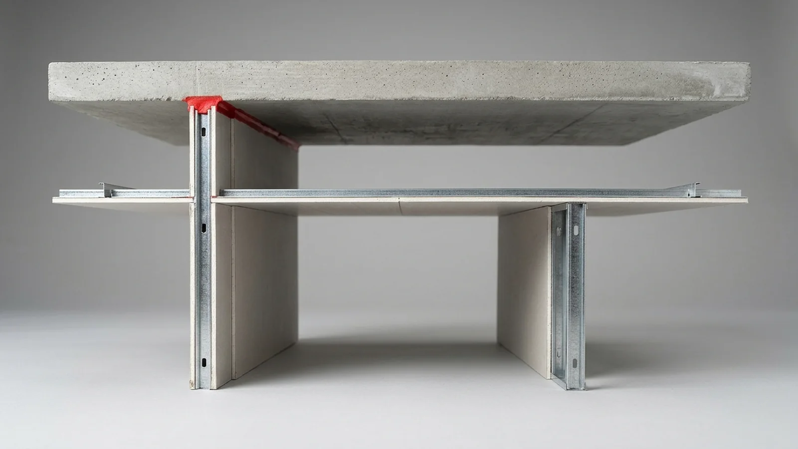
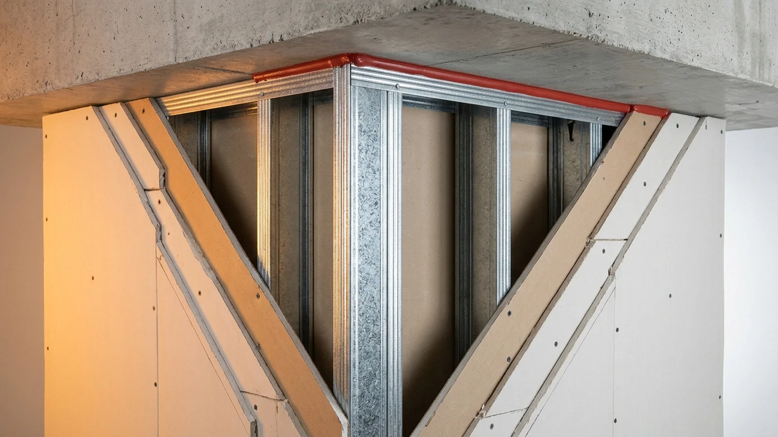
Where a non-load-bearing steel-stud wall runs up to the underside of an overhead floor assembly, that top connection is a head-of-wall joint. Firestopping is installed along head-of-wall joints and linear gaps between a fire-resisting wall and the floor above so the partition forms a complete barrier to fire and smoke spread.
How are electrical boxes, pipes, and ducts firestopped under ASTM E814?
Electrical cables and boxes, plumbing pipes, and HVAC ducts routinely cross stockroom and demising walls during a store build-out. Because ASTM E119 excludes electrical receptacle outlets, plumbing pipes, and other conventional openings unless tested inside the wall specimen, penetrations through fire-resistance-rated walls must be protected by listed firestop assemblies evaluated under ASTM E814.
Firestopping seals around electrical, mechanical, and structural penetrations so the wall keeps impeding fire and smoke without collapsing or losing integrity at the hole. Firestop materials are not rated by themselves: the rating comes from combining materials for the penetrating item and the rated wall or floor, such as a layer of caulking over packed mineral wool, and the arrangement rather than the caulking carries the rating. Each opening in a fire-resistance-rated wall must have a certification listing, and deviating from the listed arrangement can lower the wall’s fire-resistance rating. Improvised seals created on site without a listing receive no code compliance credit, and an insulation product whose active listing is only for a flame-spread rating is unacceptable for firestopping.
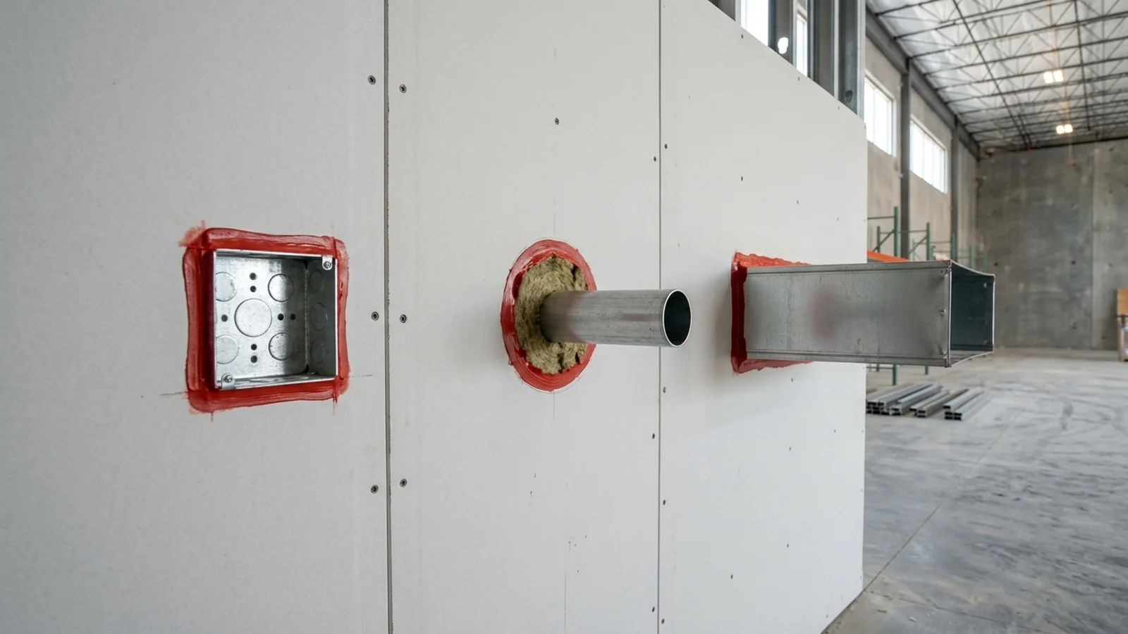
Under ASTM E814, firestop systems intended for openings in ASTM E119 walls and floors undergo both a standard time-temperature fire test and a hose stream test, and performance depends on the exact assembly tested, including the number, type, and size of penetrations and the wall or floor construction receiving them. Two primary ratings come out of ASTM E814:
- The F rating is based on flame occurrence on the unexposed surface of the firestop system.
- The T rating is based on temperature rise as well as flame occurrence on the unexposed side of the firestop system.
In the encyclopedia description of a firestop test, meeting the heat and smoke limit sets the F rating, the time until a specified average heat rise sets the FT rating, and a passed hose-stream test allows an FTH rating, with the lowest of the three determining the overall rating. Among national fire-test regimes, hose-stream testing is described as unique to Canada and the United States. An ASTM symposium paper published on 01 January 1963 examined why the hose-stream test was required in ASTM E119 acceptance or rejection and noted that the computed stream force was below the levels serving as a stability test for walls and partitions. ASTM E814 similarly notes that its hose-stream external-force measurement does not determine how a firestop performs under actual fire loads such as failed cable support systems or falling debris.
Before matching a submittal sheet to an opening on the shop drawing, check two explicit scope boundaries in ASTM E814: Test Method E814 does not apply to membrane penetrations of a floor-ceiling or roof-ceiling assembly tested as part of that assembly under ASTM E119, and it does not apply to membrane penetrations of load-bearing walls.
Storefront partition refit handoff checklist
Before closing up the second face of gypsum board or signing off on rough-in inspections during a retail build-out, verify each partition assembly item against the approved drawings and certification listings:
| Refit handoff item | Field check against the approved drawing and certification listing |
|---|---|
| Assembly listing and wall class | Confirm the assigned certification listing number, required hourly duration, and wall classification (fire wall, fire barrier, or fire partition) specified by the locally applicable building code and project drawings. |
| Gypsum board type, layers, and faces | Check that the installed Type X or Type C board formulation, sheet thickness, sheet width, and layer count on both faces of the partition match the tested assembly tolerances. |
| Steel stud size and spacing | Measure cold-formed galvanized steel stud dimensions and on-center stud spacing rather than assuming framing from a different hourly assembly carries over. |
| Fastener length and joint stagger | Verify base-layer and face-layer drywall screw lengths and edge, end, and intermediate stud spacings, with vertical joints landed over studs, staggered on opposite wall faces, and offset between base and face layers in multi-layer walls. |
| Top-of-wall continuity and head-of-wall stop | Confirm that fire barriers extend continuously through concealed ceiling spaces to the deck above with a listed head-of-wall linear joint firestop, or that any fire partition stopping at a ceiling meets a ceiling rated at least as high as the partition. |
| Listed firestop matched to each opening | Match every electrical box or cable, plumbing pipe, and HVAC duct opening to a certification listing for that wall construction and the tested penetrant count, type, and size, rejecting unlisted field seals or flame-spread-only insulation. |